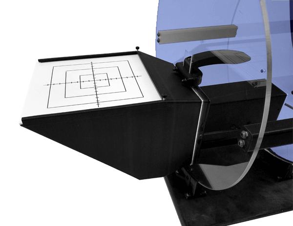
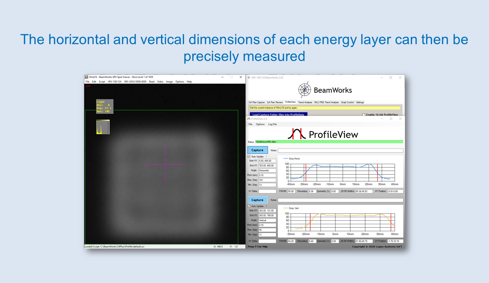
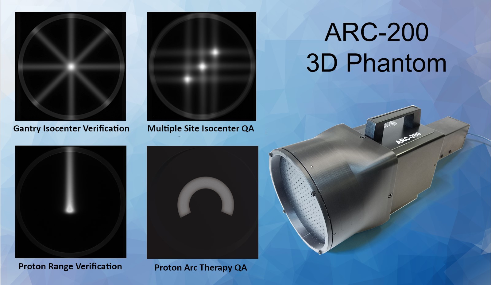
3D and 2D digital camera phantoms perform end-to-end measurements with superior precision and speed.
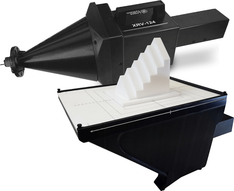
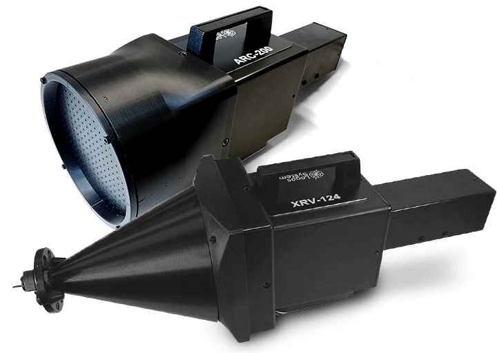
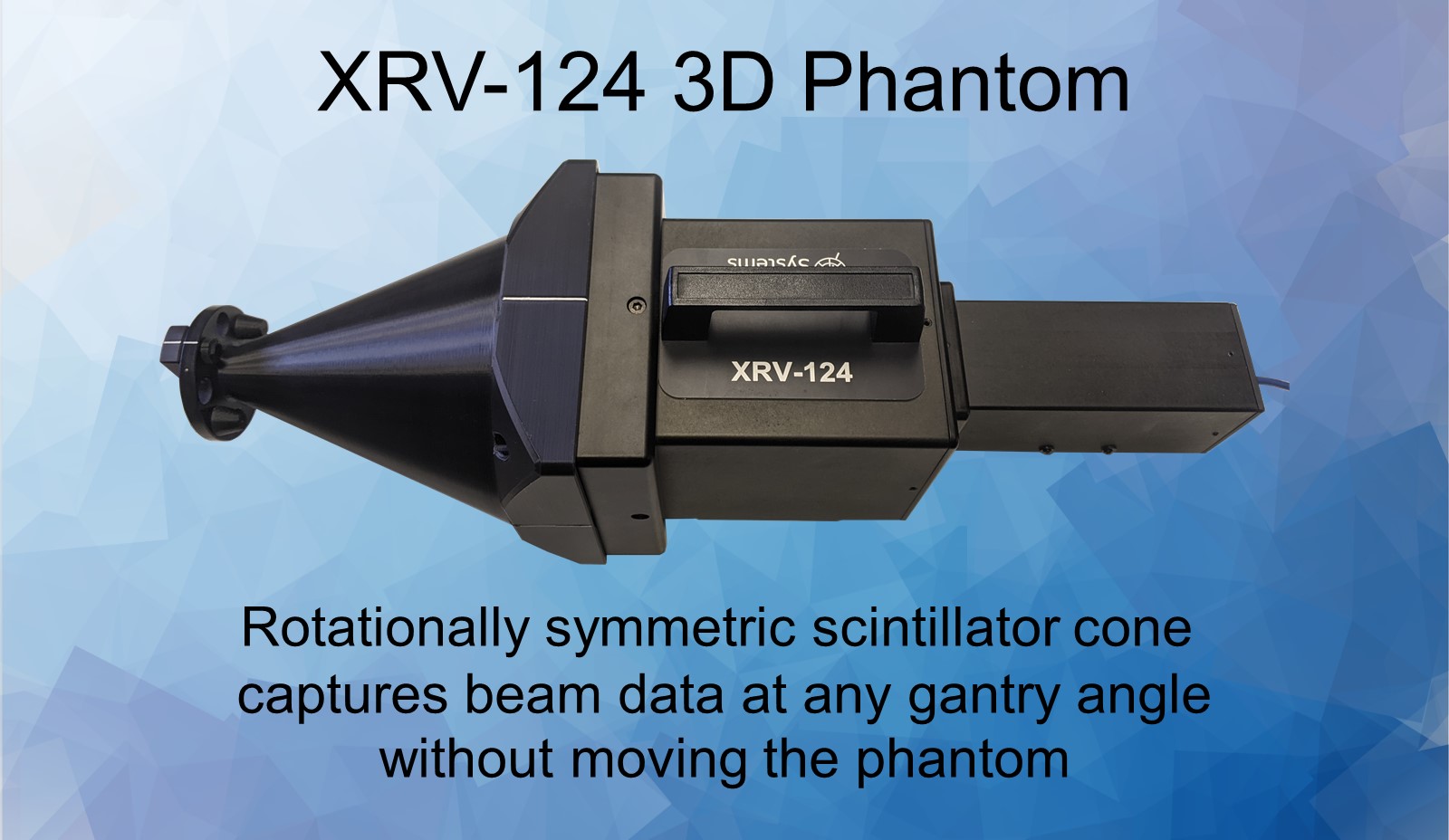
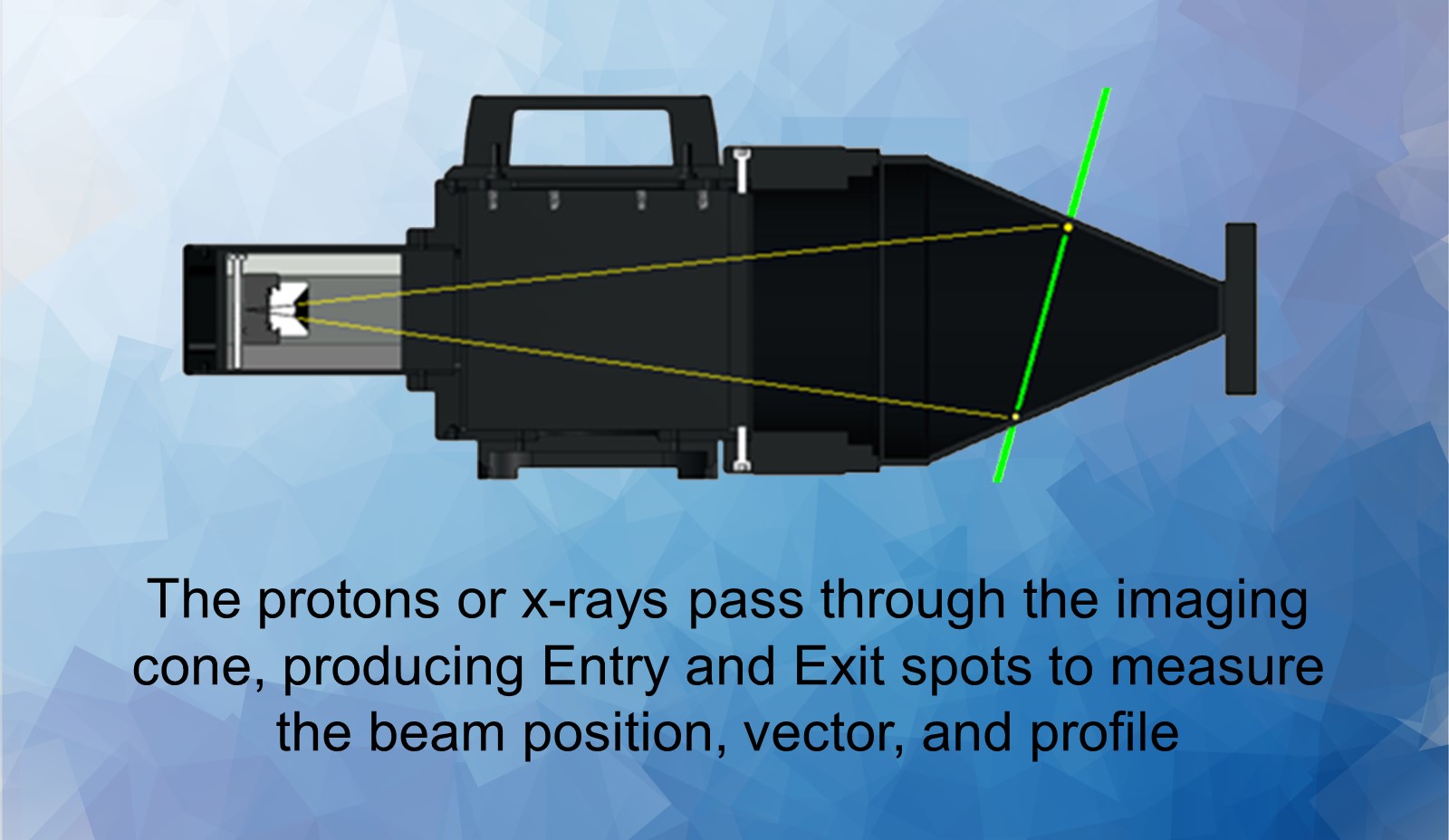
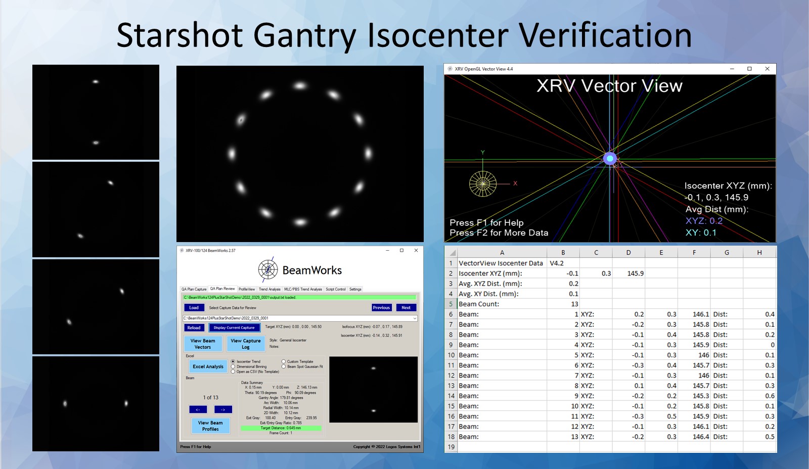
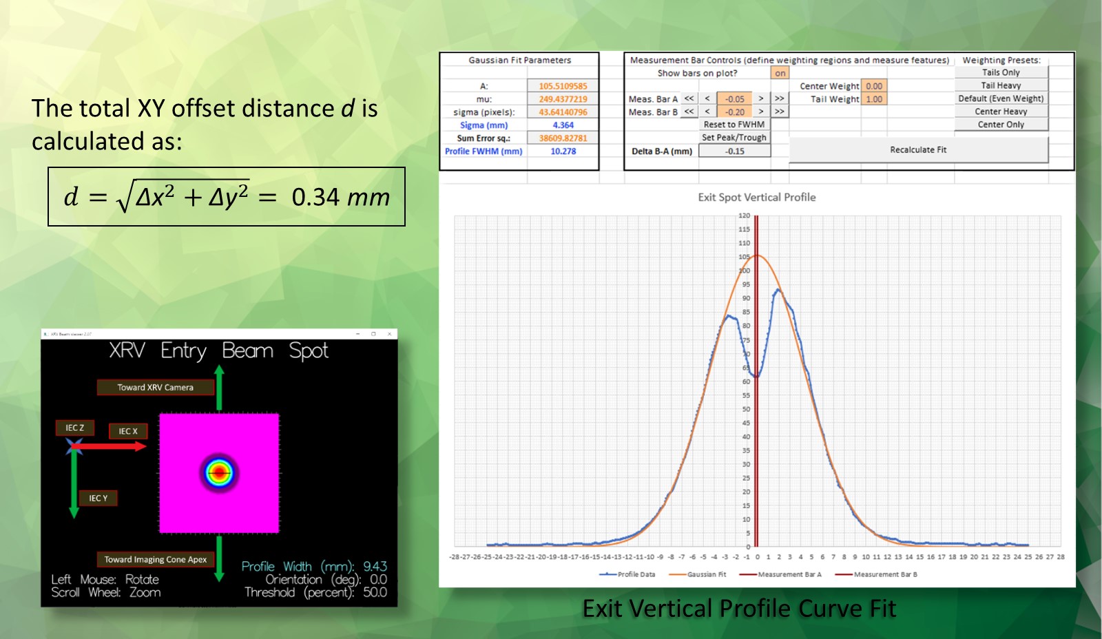
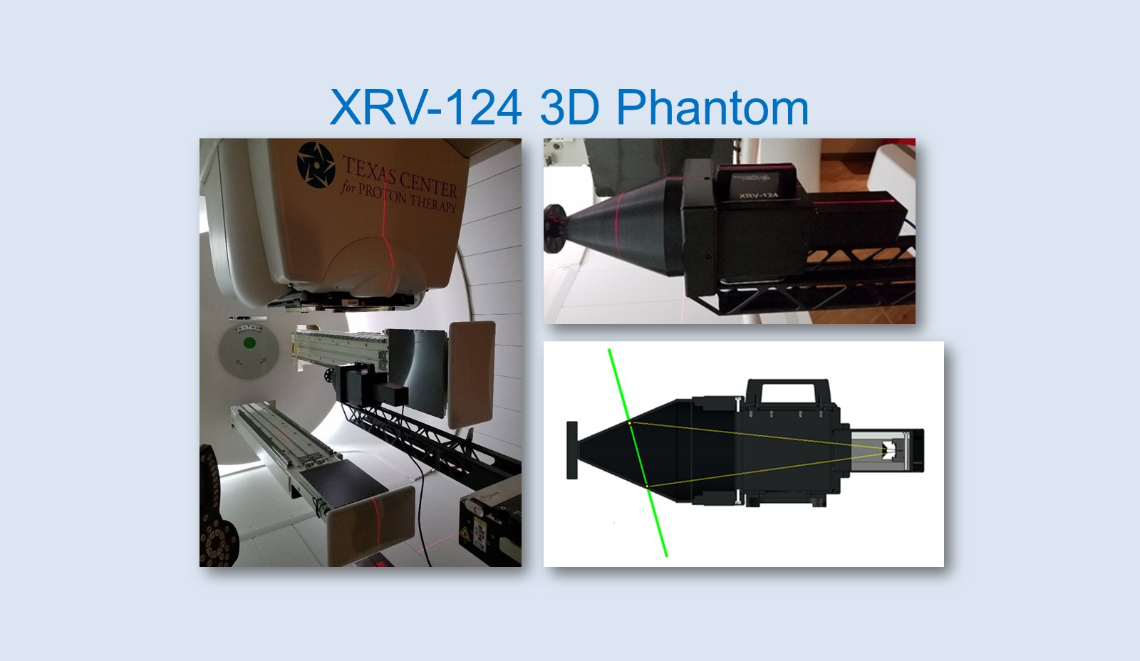
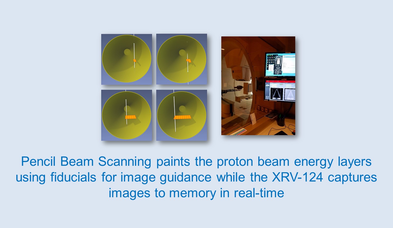
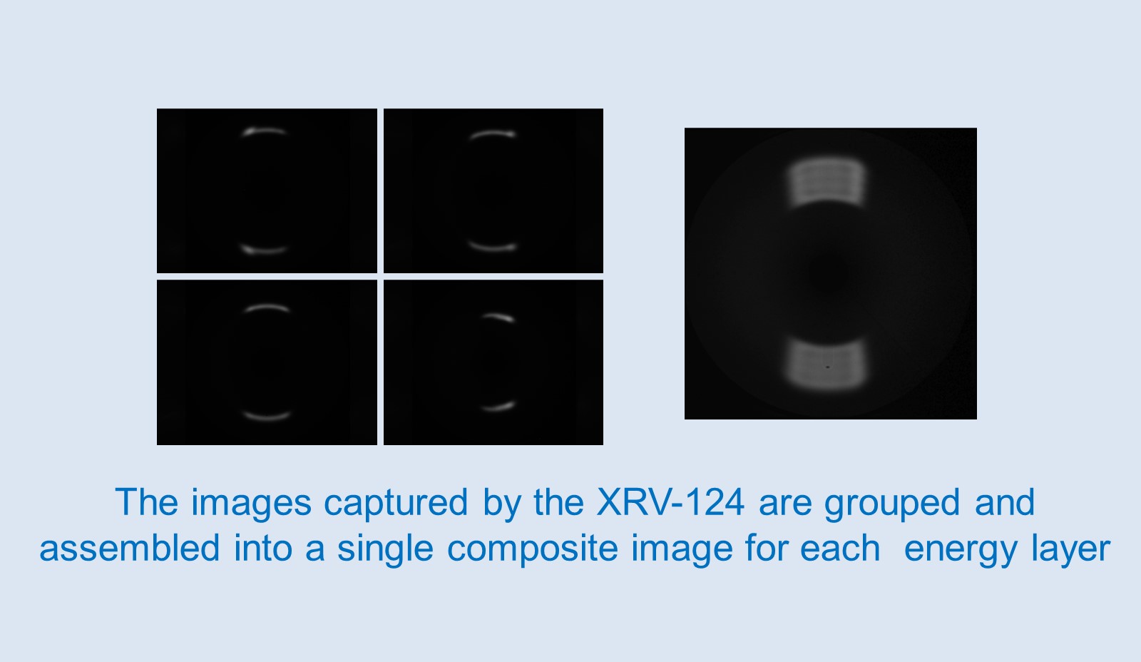
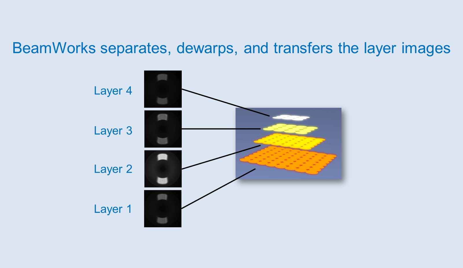
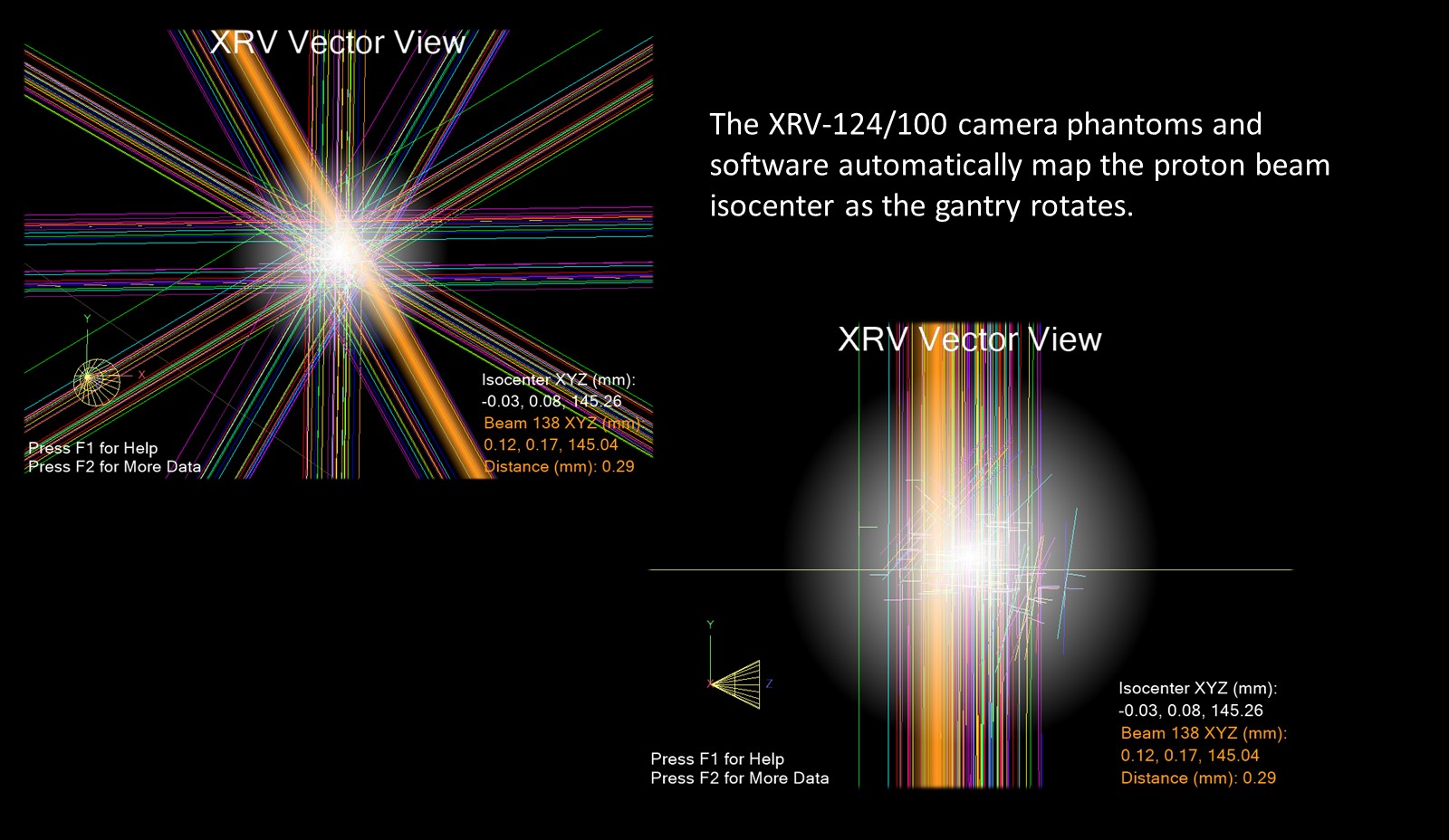
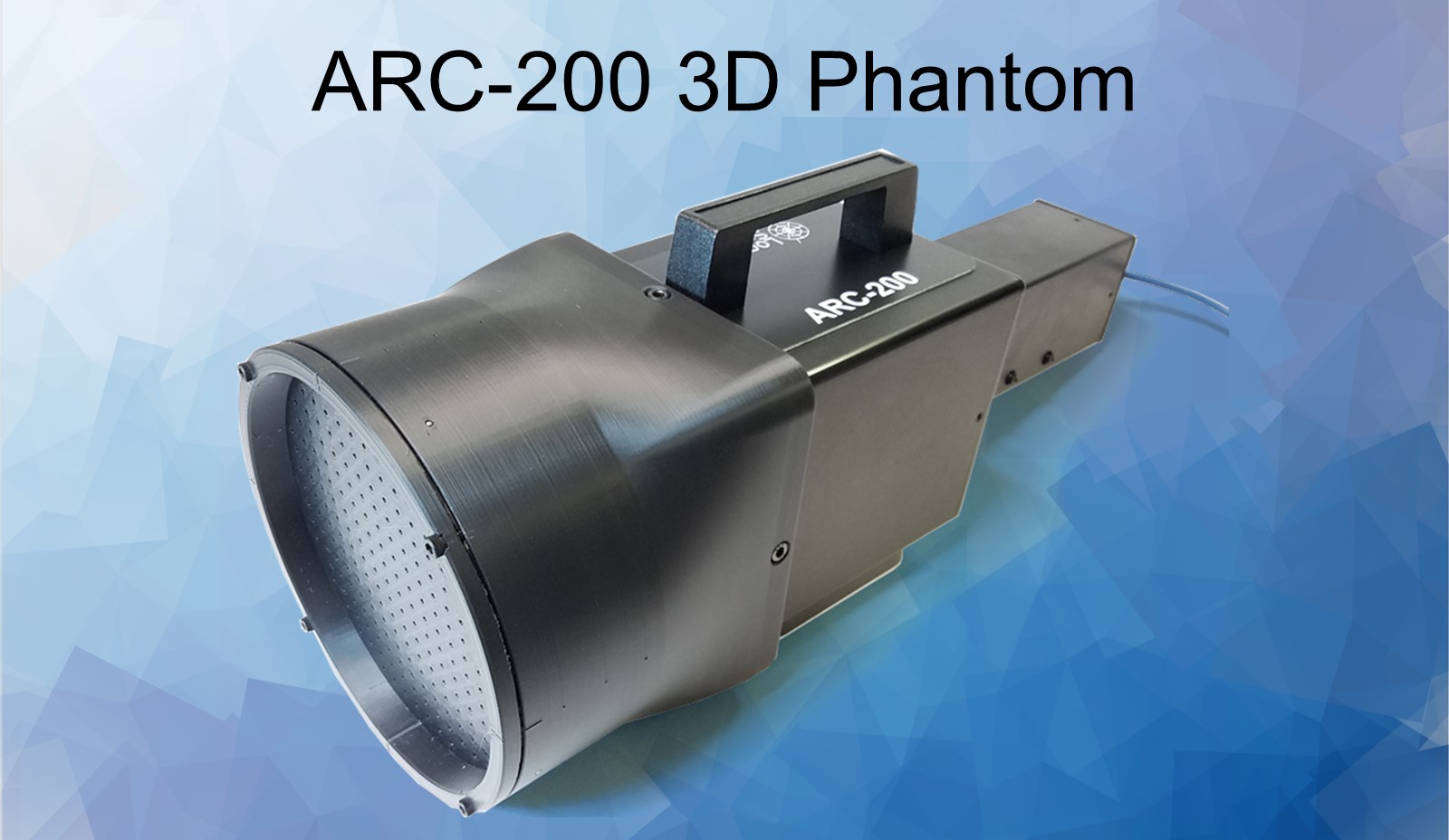
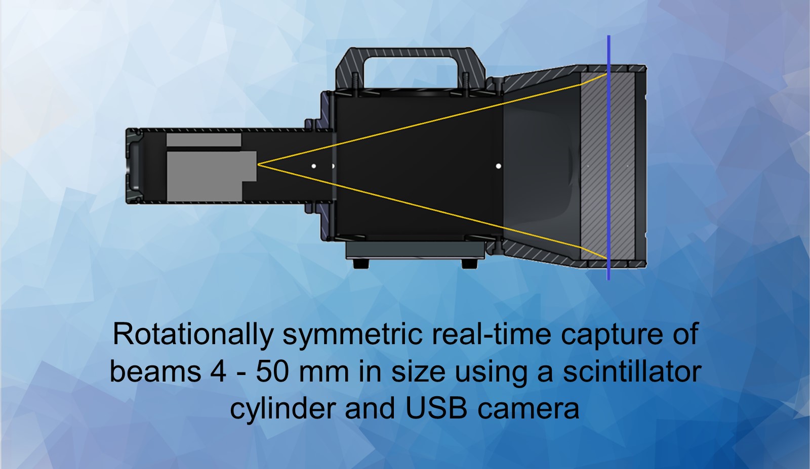
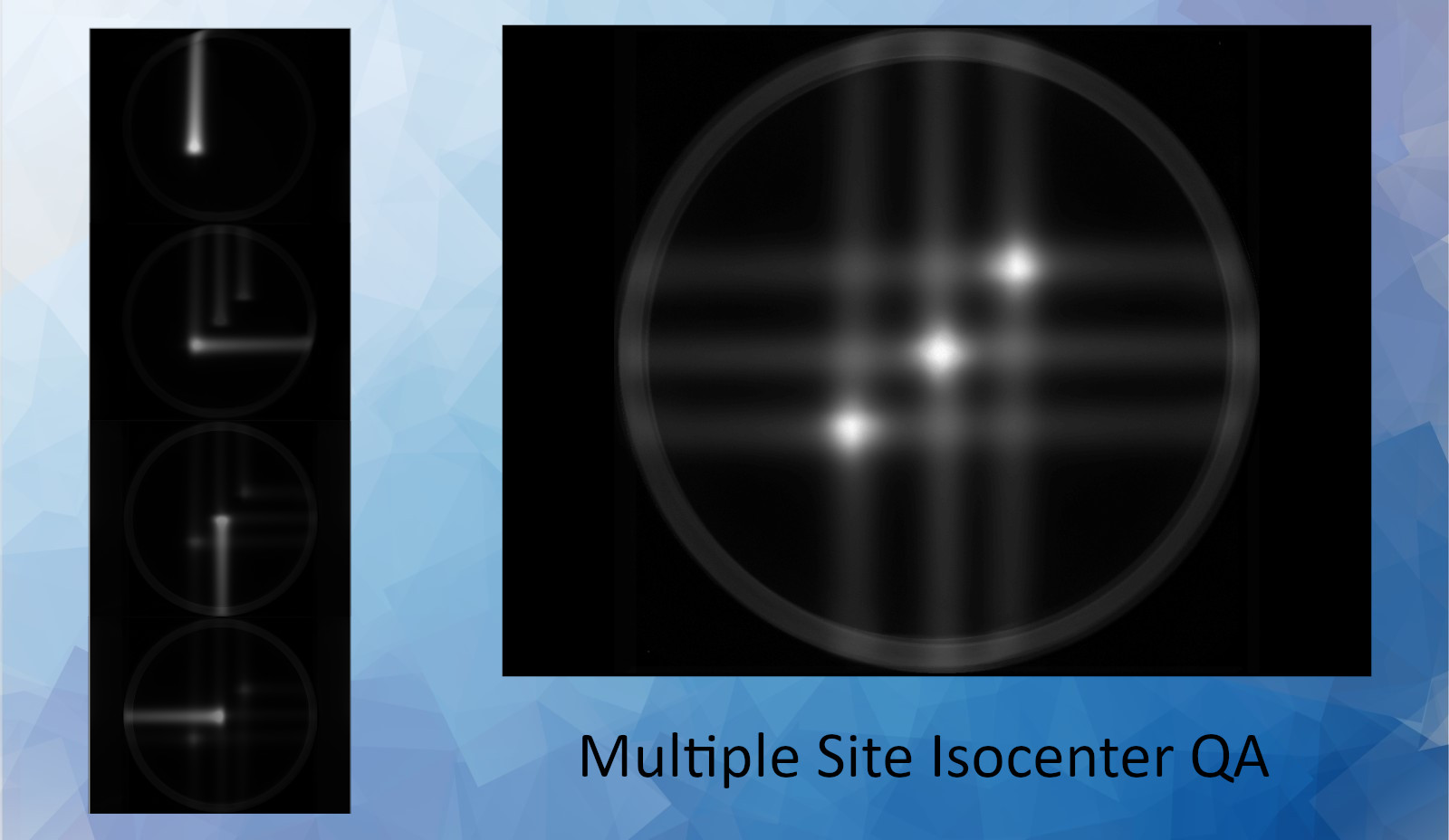
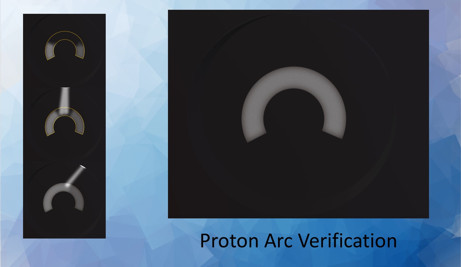
Real-time Proton and X-ray 3D beam vector and profile capture over 360 degrees of rotation.
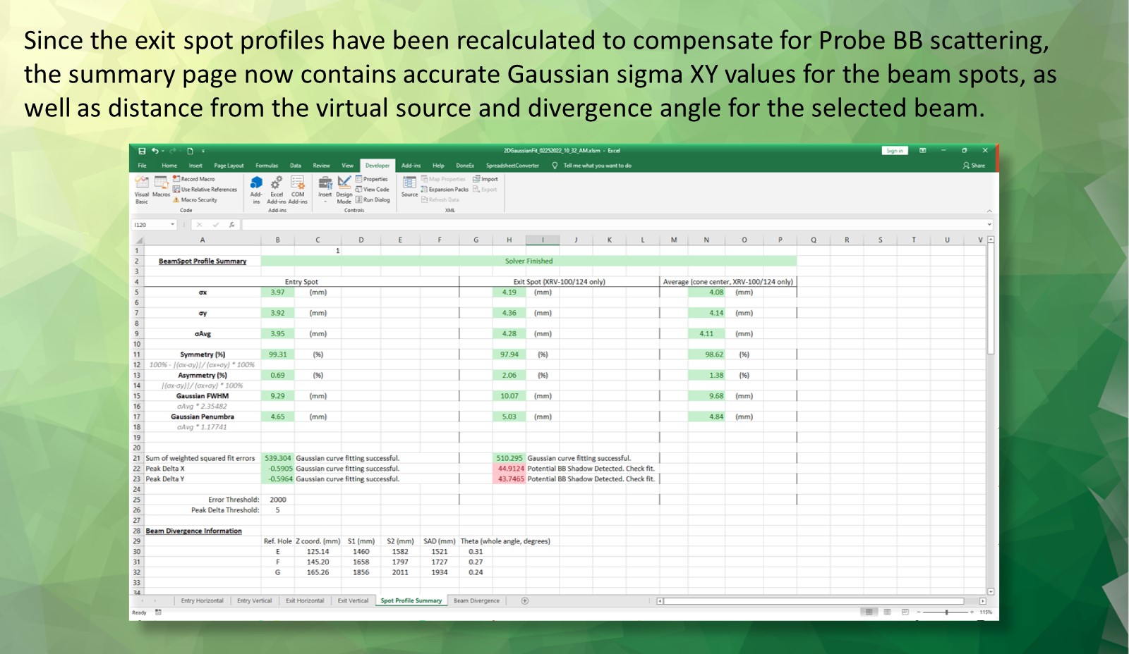
Combine high-energy radiation detection with precision two-dimensional metrology to form a completely electronic alternative to film-based measurements.
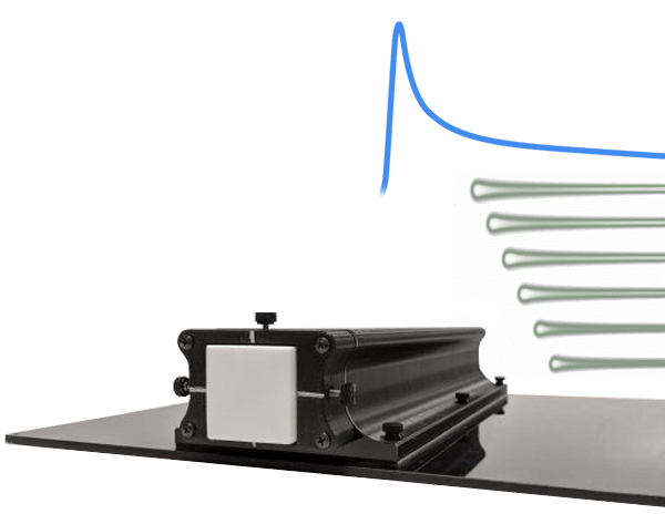
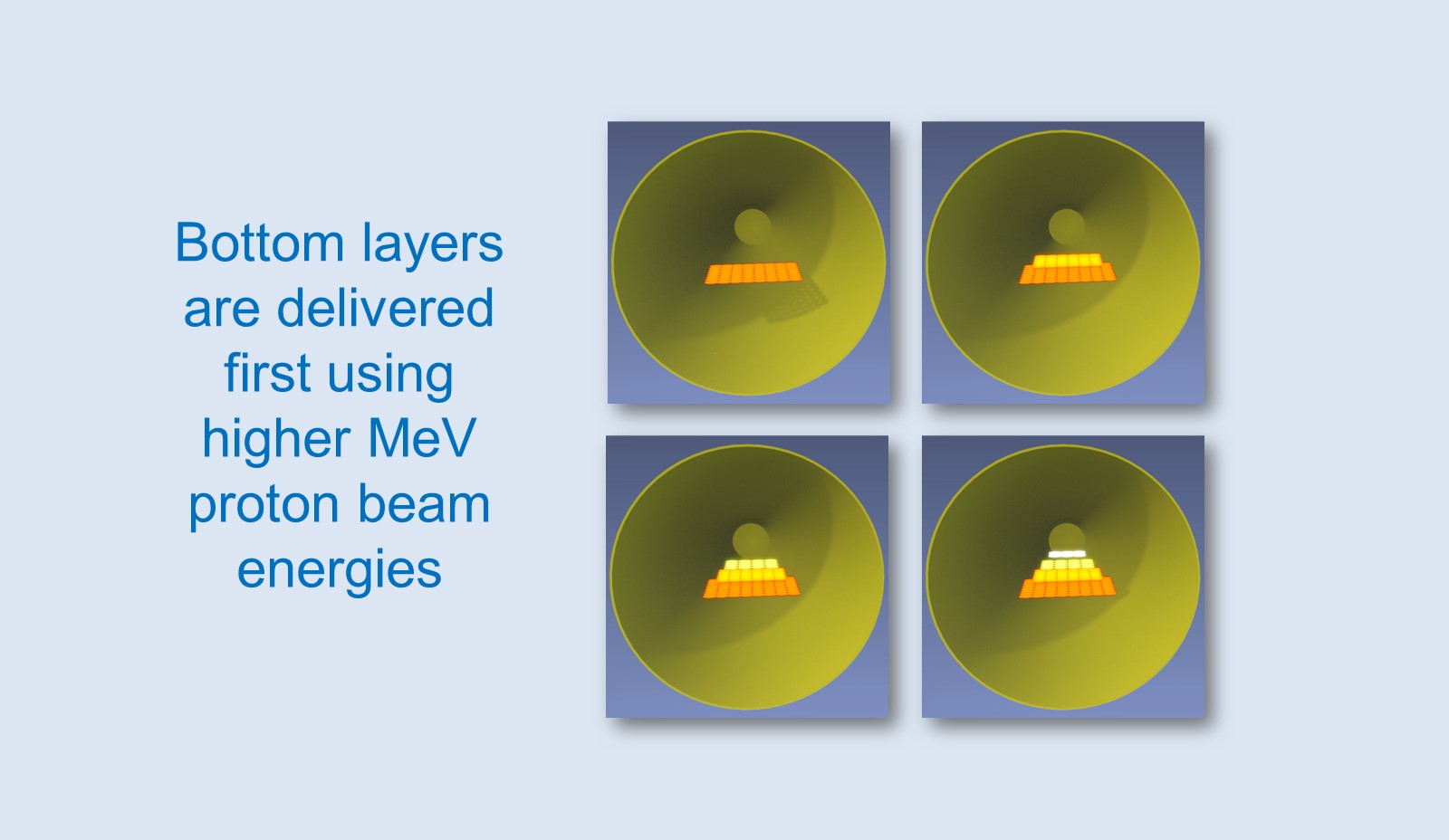
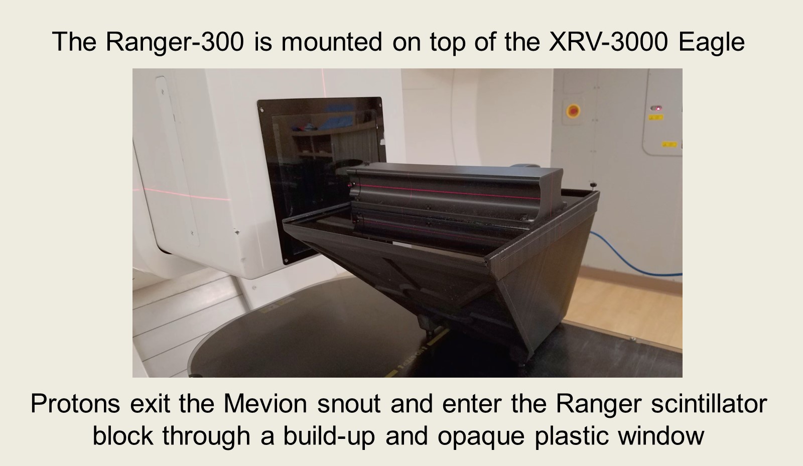
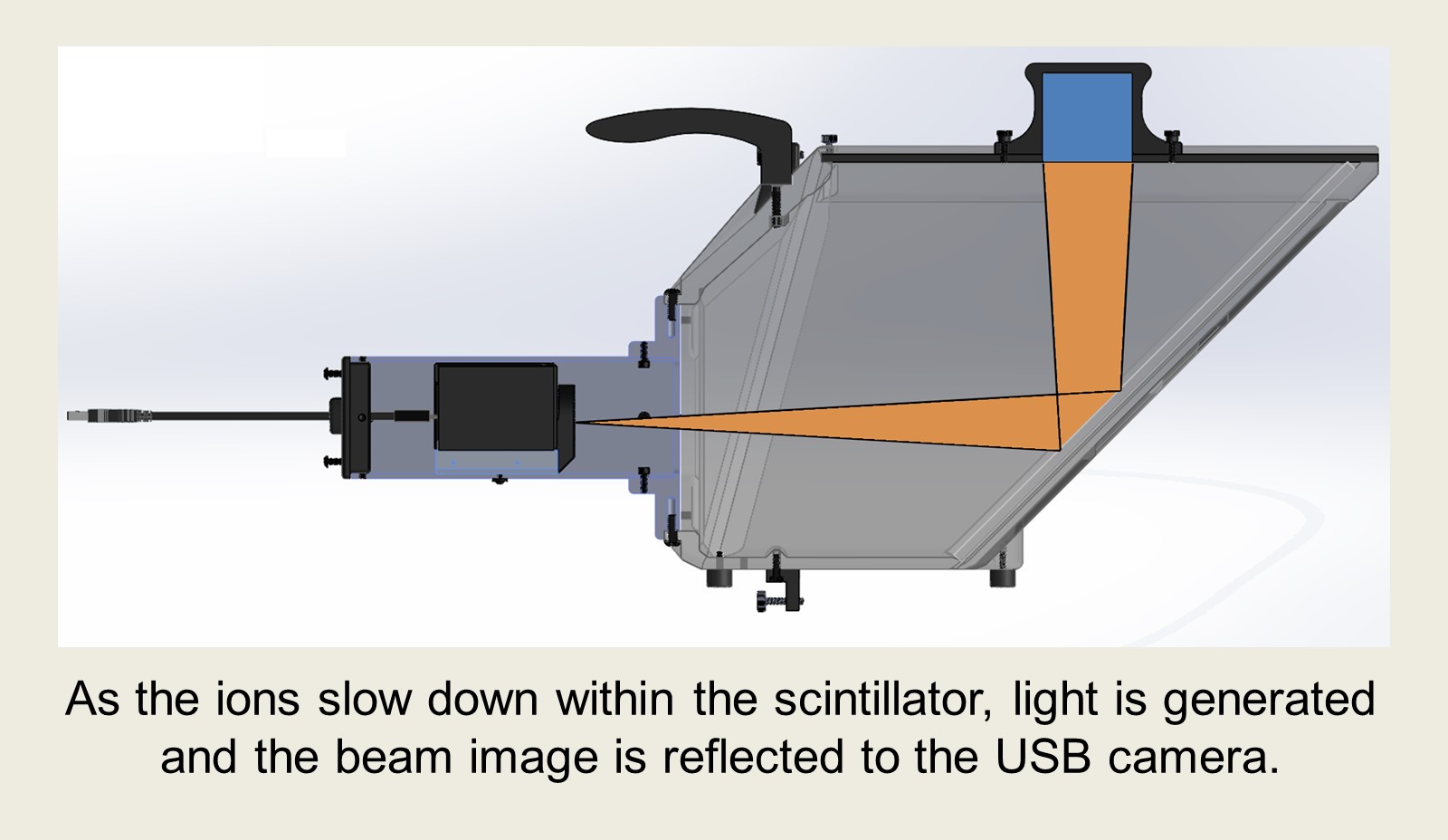
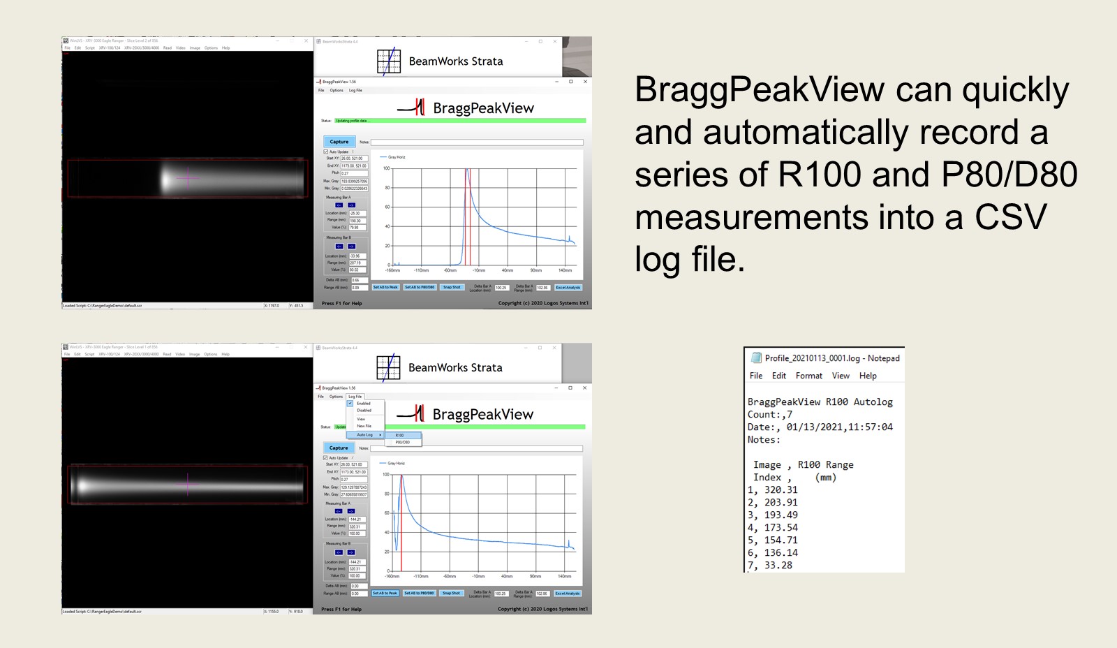
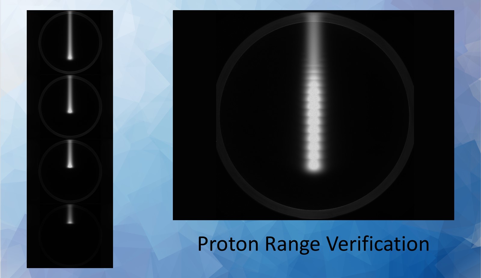
A module that mounts onto the XRV-3000 Eagle or XRV-4000 Hawk for the purpose of imaging the Bragg peak of proton and heavy ion beams.